The worst case turning time is when the servo is holding at the minimum rotation and it is commanded to go to maximum rotation. This is the time it takes from the servo to change from one position to another. Another parameter that varies from servo to servo is the turn rate. When a pulse is sent to a servo that is less than 1.5 ms the servo rotates to a position and holds its output shaft some number of degrees counterclockwise from the neutral point.

Servos will not hold their position forever though the position pulse must be repeated to instruct the servo to stay in position.


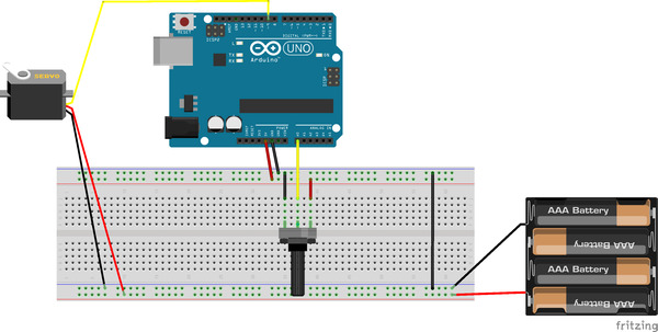
Besides supplying supply voltage (on the red wire) for the motor to pull from, a specific signal called a PWM Signal must be sent on the signal wire (usually yellow or white). How Do I Control a Servo? – Unlike brushed DC motors, servos cannot be run by simply applying a voltage. Now, you should see the servo rotate from 0 to 180 degrees, and then do it in the opposite direction.Answered By: Charles Sanders Date: created: Mar 03 2022 PinMode(servopin,OUTPUT) //Set the servo interface as the output interfaceģ. Compile the program and upload to Arduino UNO board Int pulsewidth=(angle*11)+500 //The angle is converted to a pulse width value of 500-2480ĭigitalWrite(servopin,HIGH) //The servo interface level to the highestĭelayMicroseconds(pulsewidth) //The number of microseconds of the delay pulse width valueĭigitalWrite(servopin,LOW) //The servo interface level to lowĭelayMicroseconds(20000-pulsewidth) //20000 can be replaced: "frequency = 1 / (20000/1000000)" Void servopulse(int angle)//Define an impulse function Int angle =0 //Angle of rotation of the servo Int servopin = 9 //Define servo interface digital interface 7 Be sure to connect the grounds of the Arduino and external power supply together.Ģ. The ground wire is typically black or brown and should be connected to a ground pin on the Arduino board. Usually the signal pin is yellow, orange or white, and should be connected to a digital pin on the Arduino board. Note that the servo motor draws a considerable amount of power, if you need to drive more than one or two servos, you’ll probably need to power them with an extra supply (i.e. The power wire is typically red, and should be connected to the 5V pin on the Arduino board. The servo motor has three wires: power, ground, and signal.

So we provide the following method: adjust corresponding frequency according to different servos. Different types of steering gear has different operating frequency. Through our study different steering gears were found. We found that if the Arduino provided by the library was used, some of the servo can not accurately rotate the angle we need. In this section, we will use the new method to control the servo.


 0 kommentar(er)
